As someone who likes to to my research before I jump into something, the repair of bricked LT1 PCMs was a topic that was rather light on detailed instructions.
Over the next few weeks I’d like to help that by posting a series of articles and pictures along with links to the items one would need to purchase to recreate what I have done.
By the end of the series I hope to create a “living document” that compiles all of my knowledge with all of the LT1 community’s knowledge to help keep these cars on the road and the PCMs out of the dumpster.
In my reading the first thing I found was that the 1996-1997 OBDII ECMs are dual flash chip units. These flash chips are known as the “T” side and the “E” side. This becomes important because there is a rumor floating around the internet that the “communications” portion of the calibration file is held exclusively in the “T” side flash chip and that you only need to socket and manually burn that side’s EEPROM to restore communication to the PCM.
I’m not here to call anyone a liar, however, in my experience with OBDII PCMs, I have never been able to reflash a unit through the OBDII port that has not previously been manually reflashed on both the “E” side chip as well as the “T” side chip.
My advice is do both sides, and you won’t regret it.
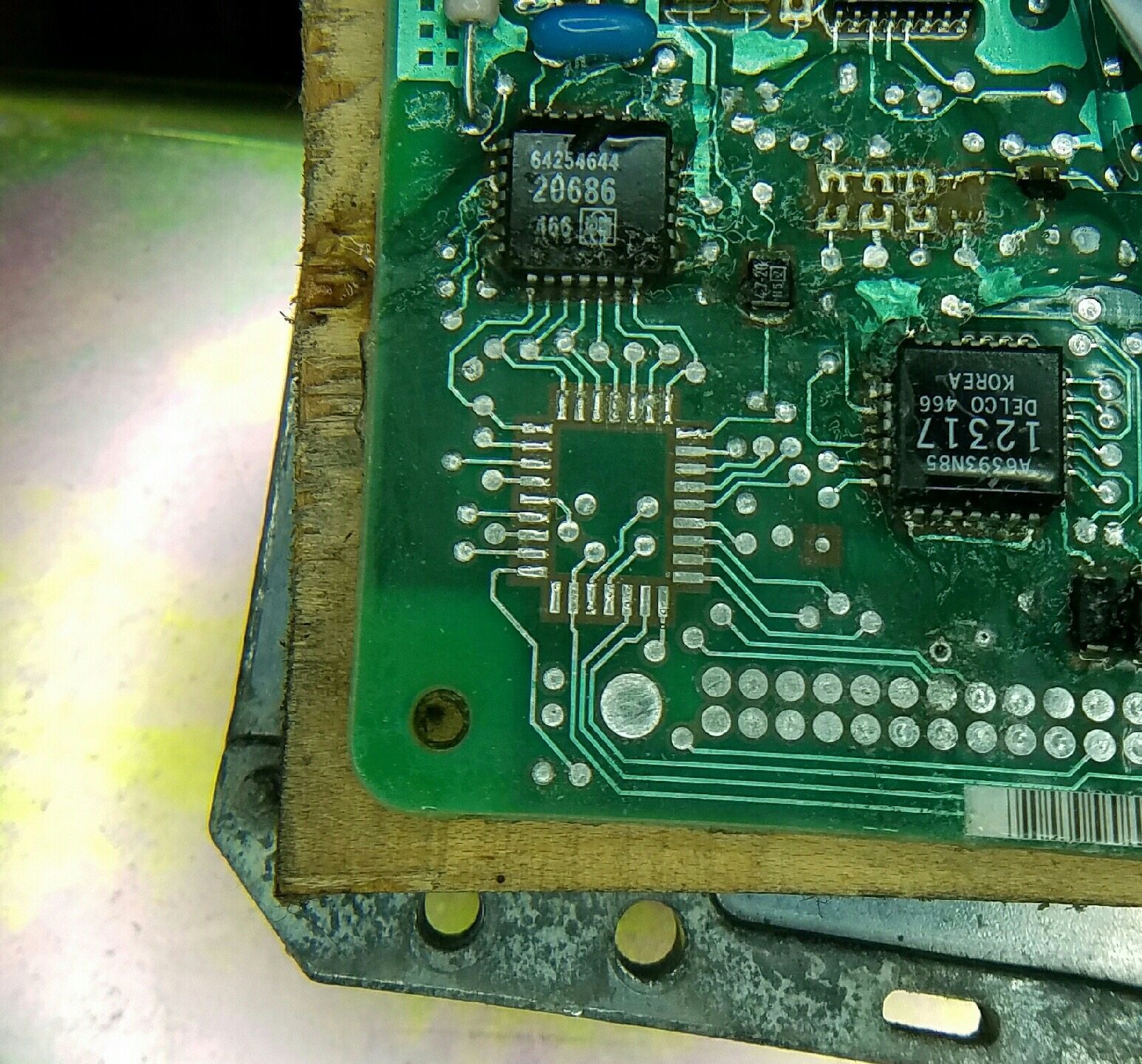
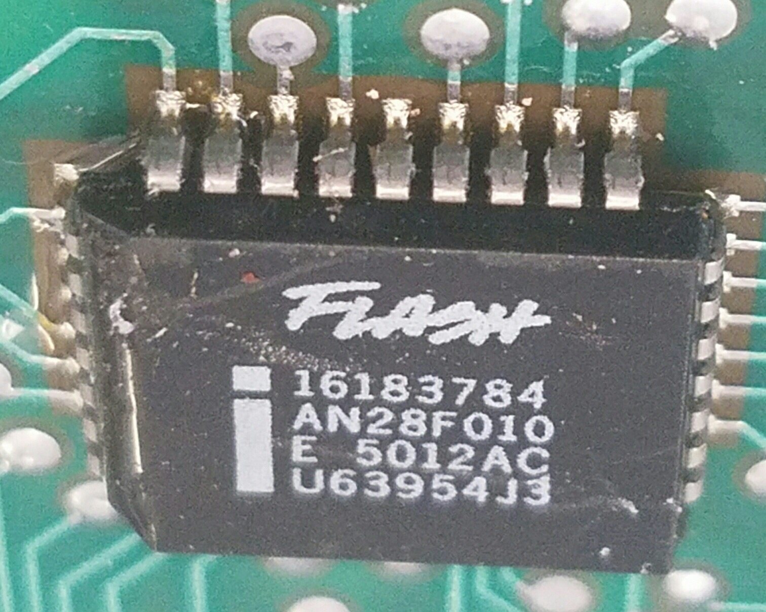
Moving on to intelligence gathering mode, I disassembled a bricked PCM to find out what I was up against. In this article I will focus on the “T” side only. The “T” side flash chips are Intel AN28F010 which are a PLCC32 type socket. Since I knew that is what I was going to need, I hopped on eBay and ordered a couple dozen PLCC32 sockets, 20 flash flash chips, and some .010″ solder.
 Moving on to the disassembly process I’d like to give credit to GoldSSWagon for the inspiration to use a heatgun to desolder the old flash chip.
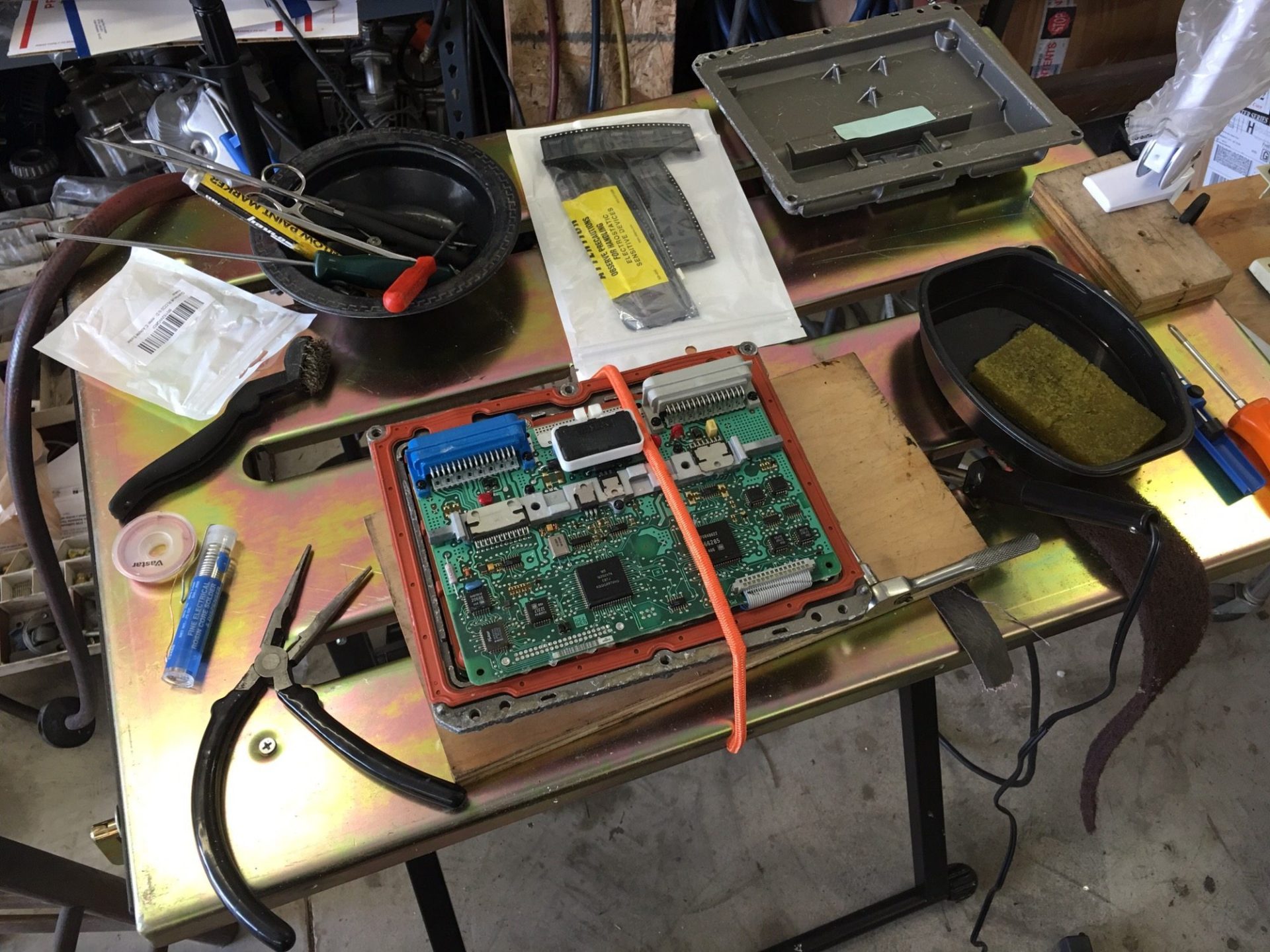
I ordered Cool Gel Spray from Amazon to protect the surrounding components from heat and I covered the rest of the PCM board with aluminum foil.
I used a porter-cable variable speed and variable temp heat gun to put direct heat on the flash chip while ever so lightly lifting the chip with a 90° pick. As GoldSS mentions, be EXTREMELY gentle during this process or you will remove the solder pad from the PCMs printed circuit board and likely create a PCM shaped paper weight.
Here is the workstation set up
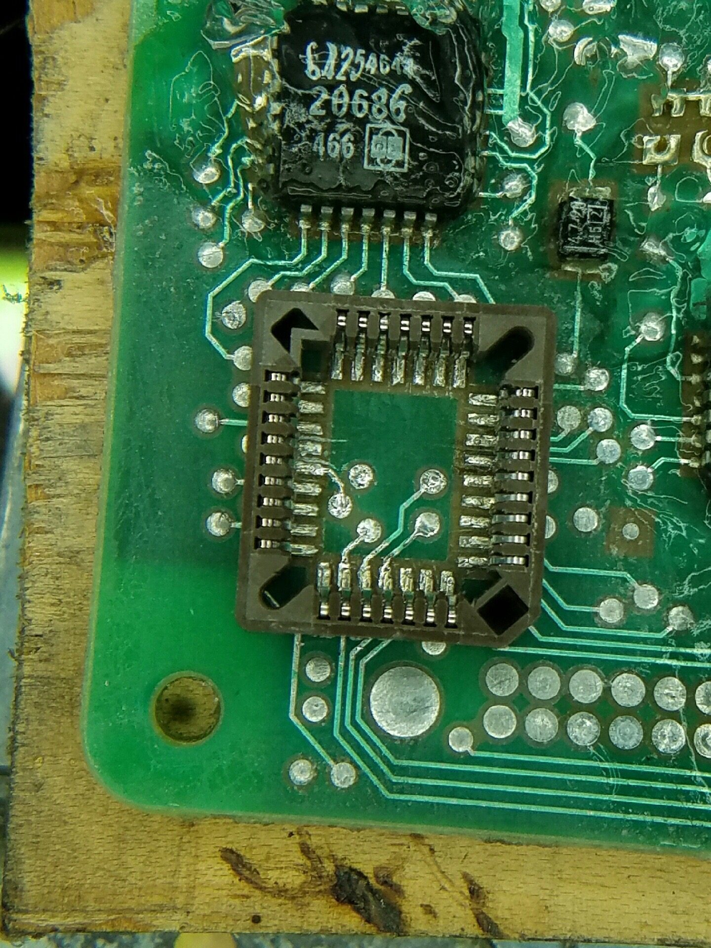
Here is the desoldered and cleaned PCM board. I used solder wick to remove the excess original solder. I also used a brand new small wire brush and isopropyl alcohol to scrub the silicone coating off of the board surrounding the flash chip.